Your own game console with embedded Rust
A short intro into Rust + embedded + fun


So you want to make a game console, ayy?
My company has this dev kit used for onboarding and student internships, and there are a few pre-existing demos for it using RTOS-es, writing device drivers and similar stuff - but I wanted something cooler, and is there anything cooler than your game console? I think not. So it was set, I will build one, and do it in Rust because why not. It will also provide a starting point for anyone in Byte Lab interested in Rust on embedded, which would otherwise come with a steeper entry curve.
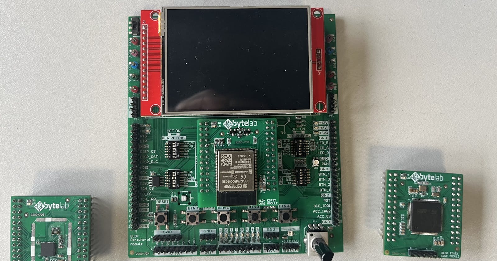
The Dev Kit
The dev kit comes equipped with an ILI9341 powered 320x240 display, 4 buttons, an I2C expander, a buzzer and a bunch of other stuff not used in this demo. Additionally, we connect a 4x4 matrix keypad to the expander IOs.
The processor is exchangeable between (for now) one of ESP32, NRF52 and STM32. This means that this project has to support 2 different architectures (xtensa and arm) and 3 different vendors.
CHIP-8
To be honest, this is kind of a cheat, but I didn't design or write anything on my own. I just ported starrhorne's excellent CHIP-8 Rust implementation to run on all of our different dev kit architectures.
This ended up making the project a VM (virtual machine) which runs premade images available from everywhere! The whole internet is filled with C8 game ROMs, albeit the games are pretty basic. I was able to find Tetris, Pong, Space Invaders, Breakout and more. A lot was found in this repo.
Setting up the environment
When I began working on this, I only had the ESP32 dev kit core, so that's what I used. Initially, I implemented all of the functionality like this and only then went on to make the application portable.
The ESP32 setup was pretty straightforward, following the instructions provided by the esp-rs repository.
Getting the display working
This turned out to be easy by utilizing this ili9341 crate. On the ESP32 the code looked something like this:
#[xtensa_lx_rt::entry]
fn main() -> ! {
    // Basic stuff
    let peripherals = Peripherals::take();
    let mut system = peripherals.DPORT.split();

    // Use 240MHz clock
    let clocks = ClockControl::configure(system.clock_control, CpuClock::Clock240MHz).freeze();

    // Get RTC and TIMG objects
    let mut rtc = Rtc::new(peripherals.RTC_CNTL);
    let timer_group0 = TimerGroup::new(peripherals.TIMG0, &clocks);
    let mut wdt0 = timer_group0.wdt;
    let timer_group1 = TimerGroup::new(peripherals.TIMG1, &clocks);
    let mut wdt1 = timer_group1.wdt;

    // Disable the RTC and TIMG watchdog timers
    rtc.rwdt.disable();
    wdt0.disable();
    wdt1.disable();

    // Initialize the io objecct
    let io = IO::new(peripherals.GPIO, peripherals.IO_MUX);

    // Display pins
    let l_sclk = io.pins.gpio18;
    let l_miso = io.pins.gpio19;
    let l_mosi = io.pins.gpio23;
    let l_cs_disp = io.pins.gpio0.into_push_pull_output();
    let l_dc = io.pins.gpio16.into_push_pull_output();
    let l_rst = io.pins.gpio4.into_push_pull_output();

    // Setup PWM for the buzzer via the LEDC peripheral
    let ledc = LEDC::new(
        peripherals.LEDC,
        &clocks,
        &mut system.peripheral_clock_control,
    );

    // Intialize the daly object for delays
    let mut delay = Delay::new(&clocks);

    // Initialize the display SPI
    let l_spi = spi::Spi::new_no_cs(
        peripherals.SPI2,
        l_sclk,
        l_mosi,
        l_miso,
        48u32.MHz(),
        spi::SpiMode::Mode0,
        &mut system.peripheral_clock_control,
        &clocks,
    );

    // Initialize the display SPI interface - provides generic display SPI function abstractions
    let disp_spi_if = SPIInterface::new(l_spi, l_dc, l_cs_disp);

    // Initialize the display
    let mut lcd = Ili9341::new(
        disp_spi_if,
        l_rst,
        &mut delay,
        Orientation::LandscapeFlipped,
        //Orientation::Portrait,
        DisplaySize240x320,
    )
    .unwrap();

    // Do stuff with the display
}
All the tooling worked well. To flash the device I used this command:cargo espflash flash --release --target xtensa-esp32-none-elf --monitor --port <port_path>
The only thing I didn't bother with since this was pretty straightforward was the debugger. Supposedly it works pretty well with VS Code, but I didn't have a need or the time for it. All of the limited debugging was done directly from the runner, which on a hard fault or any other type of exception - shows the backtrace.
Emulation
As I said for the emulation, I used starrhorne's code - and therefore the code on my side ended up only being a few lines, something like this:
// Loads a rom file into an array - this is done in compile time!!!
let rom = include_bytes!("../rom.ch8");

// Load the rom array into the C8 core
processor.load(rom);

// Main loop
loop {
    // C8 has 16 buttons
    let mut buttons = [false; 16];

    // Execute single C8 instruction
    let output = processor.tick(buttons);

    // Check whether the video ram was changed
    if output.vram_changed {
        // Redraw the screen from output.vram
    }

    if output.beep {
        // Buzzer on
    } else {
        // Buzzer off
    }
}
The thing I ended up having to modify is the vram_changed field and its corresponding C8 instruction - to pass the bounding rectangle of the redrawn area. For example, if only an 8x3 area was redrawn, there is no point in redrawing the whole screen. Below is the code of my modification:
fn op_dxyn(&mut self, x: usize, y: usize, n: usize) -> ProgramCounter {
    self.v[0x0f] = 0;
    let mut minx = CHIP8_WIDTH;
    let mut maxx = 0;
    let mut miny = CHIP8_HEIGHT;
    let mut maxy = 0;
    for byte in 0..n {
        let y = (self.v[y] as usize + byte) % CHIP8_HEIGHT;
        for bit in 0..8 {
            let x = (self.v[x] as usize + bit) % CHIP8_WIDTH;
            let color = (self.ram[self.i + byte] >> (7 - bit)) & 1;
            self.v[0x0f] |= color & self.vram[y][x];
            self.vram[y][x] ^= color;

            if x > maxx {
                maxx = x;
            }
            if x < minx {
                minx = x;
            }
            if y > maxy {
                maxy = y;
            }
            if y < miny {
                miny = y;
            }
        }
    }
    self.vram_changed = VramStatus::Block(minx, miny, maxx, maxy);
    ProgramCounter::Next
}
As you can see, the only difference in the output is that vram_changed is no longer a boolean, but instead an enum of either Nothing, All or Block(startX, startY, endX, endY) coordinates. (Probably should refactor that to be an Option since All is not used).
Since there is no double buffering, and everything is done in a single loop - emulation speed is related to the display & SPI latency (since this takes the longest). This is, of course, not ideal but I couldn't find any info about how other C8 implementations work, and whether this is even an issue. I found that it can sometimes be noticed, but it doesn't impact the gameplay.
LCD & Emulator + Scaling
Combining this with my working LCD, I had a visible C8 emulator good enough for running demos (apps which just draw stuff, no input needed). I needed to add scaling as well since 64x32 on a 320x240 display is tiny!
match output.vram_changed {
    // ...
    // Block redraw, from (sx, sy) to (ex, ey)
    VramStatus::Block(sx, sy, ex, ey) => {
        let width = ex - sx + 1;
        let height = ey - sy + 1;
        let new_width = width * SCALE;
        let new_height = height * SCALE;

        // This does DYNAMIC allocation!
        // It is also freed up when it goes out of scope
        let mut new_output = vec![0u16; new_width * new_height];

        for y in 0..height {
            for x in 0..width {
                let color = match output.vram[y + sy][x + sx] {
                    1 => 10000u16,
                    _ => 0u16,
                };
                for i in 0..SCALE {
                    for j in 0..SCALE {
                        new_output[(y * SCALE + i) * new_width + x * SCALE + j] = color;
                    }
                }
            }
        }

        lcd.draw_raw_iter(
            (sx * SCALE) as u16,
            (sy * SCALE) as u16,
            (ex * SCALE) as u16 + (SCALE - 1) as u16,
            (ey * SCALE) as u16 + (SCALE - 1) as u16,
            new_output.iter().map(|&e| e),
        )
        .unwrap();
    }
    // ...
}
A thing of note in the code above is that every redraw causes the dynamic allocation of a buffer which contains the rescaled pixels. This is of course not ideal, and I could have removed it, but I wanted to provide people with an example of how dynamic allocation is done in embedded no_std Rust. no_std means there is no standard library, so some of the standard functionality, eg. dynamic memory allocation, has to be provided in other ways.
Finally, there is a bit of an issue with tearing - something common with this display IC, but I didn't want to spend any time on that either since it would needlessly complicate this pretty basic example.
User input
C8 has 16 button inputs, but since this dev kit only has 4 - I provided only some. This is temporary since I'm currently waiting for a 4x4 matrix keypad to arrive.
In essence, the only thing that I did is registered those button pins as inputs and passed them to the debounced_pin crate for debouncing.
// Button GPIOs
let tmp_btn_1 = io.pins.gpio33.into_pull_up_input();
let tmp_btn_2 = io.pins.gpio32.into_pull_up_input();
let tmp_btn_3 = io.pins.gpio31.into_pull_up_input();
let tmp_btn_4 = io.pins.gpio30.into_pull_up_input();

// ...
let mut d_btn_1 = DebouncedInputPin::new(tmp_btn_1, ActiveHigh);
let mut d_btn_2 = DebouncedInputPin::new(tmp_btn_2, ActiveHigh);
let mut d_btn_3 = DebouncedInputPin::new(tmp_btn_3, ActiveHigh);
let mut d_btn_4 = DebouncedInputPin::new(tmp_btn_4, ActiveHigh);

// ...
// code below is inside the emulation loop

// Update the debouncing objects
let _ = d_btn_1.update();
let _ = d_btn_2.update();
let _ = d_btn_3.update();
let _ = d_btn_4.update();

// C8 has 16 buttons, we provide only some so fill them
let mut buttons = [false; 16];

// I kinda fit this to the game which was currently running
buttons[4] = d_btn_1.is_active();
buttons[5] = d_btn_2.is_active();
buttons[6] = d_btn_3.is_active();
buttons[7] = d_btn_4.is_active();

// Execute single C8 instruction
let output = processor.tick(buttons);
Sound
This ended up being pretty simple - just turn on or off the PWM for the buzzer pin. The thing is it's different for every single vendor since it's not covered by the embedded_hal.
// Setup PWM for the buzzer via the LEDC peripheral
let ledc = LEDC::new(
    peripherals.LEDC,
    &clocks,
    &mut system.peripheral_clock_control,
);

let mut hstimer0 = ledc.get_timer::<HighSpeed>(timer::Number::Timer0);

hstimer0.configure(timer::config::Config {
        duty: timer::config::Duty::Duty8Bit,
        clock_source: timer::HSClockSource::APBClk,
        frequency: 4u32.kHz(),
})
.unwrap();

let mut channel0 = ledc.get_channel(channel::Number::Channel0, io.pins.gpio15);

channel0.configure(channel::config::Config {
        timer: &hstimer0,
        duty_pct: 0,
})
.unwrap();

// Controlled like this, where 10 is the duty cycle value
channel0.set_duty(10).unwrap();
Adding the other platforms
To be able to do this, I first needed to abstract away all the device-specific hardware stuff. I drew the line for my abstraction layer after the initialization of raw HALs for SPI, GPIOs, delays and a lambda capture for the buzzer (just to show that it also works on embedded).
My AppContext struct ended up looking something like this, and I have a corresponding function which contains the application & drivers.
// Struct filled with generic's but they are
pub struct AppContext<
    'a,
    DISPSPI,
    DISPDCOP,
    DISPCSOP,
    DISPRSTOP,
    DELAY: 'static,
    BUZZERCB,
    GPIOI1,
    GPIOI2,
> {
    pub disp_spi: DISPSPI,

    pub disp_gpio_dc: DISPDCOP,
    pub disp_gpio_cs: DISPCSOP,
    pub disp_gpio_rst: DISPRSTOP,

    pub delay_ms: &'a mut DELAY,

    pub buzzercb: BUZZERCB,

    pub tmp_btn_1: GPIOI1,
    pub tmp_btn_2: GPIOI2,
}

// This could have been an impl but whatever, it's a single function
// Also here the generics are specialized into hals
pub fn app_main<DISPSPI, DISPDCOP, DISPCSOP, DISPRSTOP, DELAY, BUZZERCB, GPIOI1, GPIOI2>(
    ctx: AppContext<DISPSPI, DISPDCOP, DISPCSOP, DISPRSTOP, DELAY, BUZZERCB, GPIOI1, GPIOI2>,
) where
    DISPSPI: embedded_hal::blocking::spi::Write<u8>,

    DISPDCOP: embedded_hal::digital::v2::OutputPin,
    DISPCSOP: embedded_hal::digital::v2::OutputPin,
    DISPRSTOP: embedded_hal::digital::v2::OutputPin,

    DELAY: embedded_hal::blocking::delay::DelayMs<u16>,

    BUZZERCB: Fn(bool),

    GPIOI1: embedded_hal::digital::v2::InputPin,
    GPIOI2: embedded_hal::digital::v2::InputPin,
{
    // App logic (emulation loop + dev-kit drivers (display, etc...)
After that, I have a custom entry point for each setup. There the peripherals are initialized and app_main is called.
The final thing I had to do was configure the conditional compilation part of the project. There is no point in compiling all the code regardless of the platform. I solved this by setting up my Cargo.toml file to look something like this:
## Some stuff has been removed, just to keep this compact

[dependencies]
## Generic stuff, used in app
ili9341 = "0.5.0"
display-interface-spi = "0.4.1"
embedded-hal = "0.2.7"
log = "0.4.17"
## ...

## ESP32 (xtensa one) BSP stuff
esp32-hal = { version = "0.8.0", optional = true }
esp-alloc = { version = "0.1.0", features = ["oom-handler"], optional = true }
xtensa-lx-rt = { version = "0.14.0", features = ["esp32"], optional = true }
xtensa-lx = { version = "0.7.0", optional = true }
## ...

## Common ARM stuff
cortex-m-rt = { version = "0.7", optional = true }
cortex-m = { version = "0.7.7", features = [
    "critical-section-single-core",
], optional = true }
alloc-cortex-m = { version = "0.4.4", optional = true }
embedded-alloc = { version = "0.5.0", optional = true }
## ...

## STM32F407 BSP stuff
stm32f4xx-hal = { version = "0.14.0", features = [
    "rt",
    "stm32f407",
], optional = true }
## ...

## NRF52832 BSP stuff
nrf52832-hal = { version = "0.16.0", optional = true }
## ...

[features]
stm32 = [
    "cortex-m-rt",
    "cortex-m",
    "stm32f4xx-hal",
    ## ...
]
esp32 = [
    "esp32-hal",
    "xtensa-lx-rt",
    "xtensa-lx",
    ## ...
]
nrf52 = [
    "cortex-m-rt",
    "cortex-m",
    "nrf52832-hal",
    ## ...
]
As you can see everything, not inside the application code is optional, and wrapped in features. So when I compile I do eg.: rust build --release --features esp32 and it all works out.
Different entry point implementations are chosen with this macro#![cfg(feature = "esp32")], which I have in every "main" file.
Other than that, every core has a specific .cargo/config.toml and rust-toolchain.toml as well as memory.x linker file. Those I just copy into the root of the project whenever I change targets. Of course, it's not ideal and can be done with something like a wrapper script - but this works well with my IDE and rust-analyzer.
The project directory tree is therefore organized like this, where the different configs are the different cores:
.
├── Cargo.lock
├── Cargo.toml
├── README.md
├── configs
│   ├── esp32
│   │   ├── .cargo
│   │   │   └── config.toml
│   │   └── rust-toolchain.toml
│   ├── nrf52
│   │   ├── .cargo
│   │   │   └── config.toml
│   │   └── rust-toolchain.toml
│   └── stm32
│       ├── .cargo
│       │   └── config.toml
│       ├── memory.x
│       └── rust-toolchain.toml
└── src
    ├── app
    │   ├── app.rs
    │   ├── font.rs
    │   ├── mod.rs
    │   └── processor.rs
    ├── main.rs
    └── main_impl
        ├── main_esp32.rs
        ├── main_nrf52.rs
        ├── main_stm32.rs
        └── mod.rs
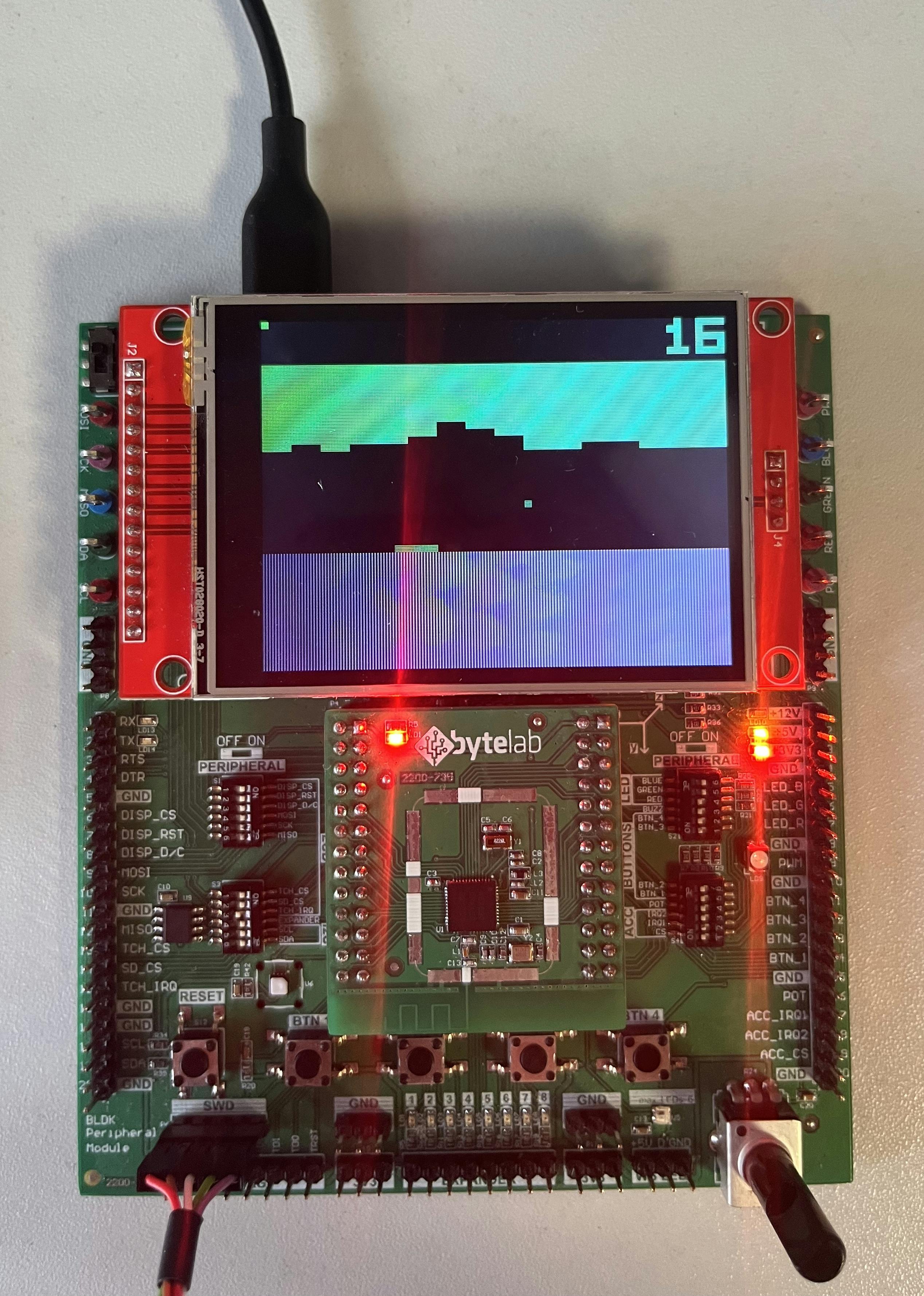
Results
Conclusion
All in all, I learned a lot during this project. My love for Rust only grew and I hope this speeds up the language's adoption by at least a little bit.
Regarding the embedded segment, I think there still is a way to go - but for something, without any manufacturer support, I am amazed by how good the ecosystem is.